**Abstract:**
A novel mesh valve with a self-elastic buffer sheet compressor is introduced. Unlike traditional designs, the central portion of the buffer sheet does not include an elastic arm but instead functions as an independent elastic body. This design reduces stress during operation, increases the self-rigidity coefficient, and enhances the spring force and overall reliability of the valve. Finite element analysis is employed to calculate the stiffness coefficient, working stress, and equivalent mass of the self-elastic buffer sheet, while a corresponding mathematical model for the valve's operational behavior is developed. The mesh valve with a self-elastic buffer sheet has been successfully applied in various large and medium-sized compressors, demonstrating excellent performance.
**Keywords:** Compressor; Mesh Valve; Self-Elastic Buffer Sheet; Reliability; Mathematical Model; Application
**Introduction**
Valves are among the most critical and vulnerable components in reciprocating compressors [1]. Mesh valves are widely used in large and medium-sized reciprocating compressors. In traditional non-friction belt mesh valves, the buffer sheet is typically supported by an elastic arm at its center, and deformation under spring force mainly occurs in this arm. However, this results in high working stress and a low rigidity coefficient. In many applications, a higher stiffness coefficient is required to increase the buffering effect through greater spring force, but excessive stress can compromise the buffer’s reliability. Traditional elastic arms struggle to meet these demands [2]. To address this, this paper presents a new mesh valve with a self-elastic buffer sheet [3].
**Structure of the Self-Elasic Buffer Sheet Mesh Valve**
As shown in Figure 1, the structure of the self-elastic buffer sheet mesh valve includes a seat, valve plate, lift pads, self-elastic buffer sheet, and a lifting limiter. The buffer sheet is designed without an elastic arm at the center, functioning as an independent elastic component. The buffer sheet is connected via tendons, and its deformation primarily occurs in the connecting bars. Additionally, the inner rings have straight slots that reduce the rigidity of the buffer sheet while allowing the valve spring to press against the valve plate.
**Calculation of the Self-Elastic Buffer Sheet**
Figure 2 shows the top view of the self-elastic buffer sheet. Under spring force, the buffer sheet deforms and experiences stress, with maximum deflection occurring at the outermost edge and maximum tensile stress at the junction between the connecting ribs and the central fixed ring. Due to the complex geometry, finite element analysis (FEA) is used to calculate deformation and stress. The stiffness coefficient $ K_s $ is given by:
$$
K_s = \frac{F_s}{W_{\text{max}}}
$$
where $ F_s $ is the total spring force, and $ W_{\text{max}} $ is the maximum deflection. Equivalent mass is calculated using Rayleigh’s method, based on static bending mode shapes. For a buffer sheet with specific dimensions (e.g., outer diameter 332 mm, thickness 2 mm), ANSYS simulations show a stiffness coefficient of 3214 kN/m and an equivalent mass of 0.1318 kg. The maximum tensile stress at 1 mm deflection is 4416 MPa. Compared to traditional designs, the self-elastic buffer sheet exhibits higher rigidity, better buffering, and improved reliability.
**Mathematical Model of the Mesh Valve Working Process**
The mathematical model of the mesh valve with a self-elastic buffer includes equations of motion, energy conservation, continuity, and boundary conditions. During the opening or closing process, the valve’s motion equation is:
$$
M_v \ddot{h} + F_v = A_p p_s - A_p p
$$
where $ M_v $ is the equivalent mass, $ h $ is displacement, $ A_p $ is the effective area, and $ p_s $, $ p $ are pressures in the suction chamber and cylinder, respectively. When the valve collides with the buffer, the motion equation changes, and the collision is modeled using a rebound coefficient $ C_R $. The gas flow through the valve is governed by one-dimensional, adiabatic flow, leading to the energy conservation equation:
$$
K \frac{dV}{dt} = m R T_s \frac{d}{dt} \left( \frac{1}{V_s} \right)
$$
Boundary conditions and initial conditions are set based on the valve’s opening angle and gas pressure. Numerical solutions using the fourth-order Runge-Kutta method provide insights into valve movement, flow capacity, and energy loss.
**Application of the Self-Elasic Buffer Sheet Mesh Valve**
This type of valve has been successfully applied in multiple large and medium-sized compressors. For example, in the H22III-165/320 nitrogen and hydrogen compressor, the first-stage valve life increased from about one month to over four months after the upgrade. Similarly, second to fourth-stage valves saw their service life extend from two to six months. No fractures were observed after long-term operation. The valve has been widely adopted in more than 20 major compressors across China, proving its high reliability and practical value.
**References**
[1] Lin Mei, Yu Yongzhang. Valve Components. See: Yu Yongzhang editor. Volume Compressor Technical Manual. Beijing: Mechanical Industry Press, 2000
[2] Pan Shulin, Lu Zhaoxia, Zhang Zengying, et al. Compressor Technology, 2002 (5): 43–45
[3] Pan Shulin, Xie Lianhua, Yang Lin. A Compressor Valve. Chinese Utility Model Patent, ZL98217013.0, 1999
[4] Pan Shulin. Working Characteristics of Reciprocating Compressor Mesh Valves: [Ph.D. Thesis]. Xi’an: Xi’an Jiaotong University, 1996
[5] Ni Zhenhua. Vibration Mechanics. Xi’an: Xi’an Jiaotong University Press, 1989
[6] Tan Jianguo. Finite Element Analysis Using ANSYS6.0. Beijing: Peking University Press, 2002
[7] Pan Shulin, Lu Zhaoxia, Zhang Zengying, et al. Research and Application of High-Efficiency Valves in H22 Nitrogen and Hydrogen Compressors. Journal of Guangxi University, 2002, 27(4): 284–287
**Author Information**
Pan Shulin, male, born in 1970. Associate Professor of Mechanical Engineering at Xiangtan University, Ph.D. Research focus: Compressor working processes. Published 22 papers.
Gong Shuguang, male, born in 1964. Associate Professor of Mechanical Engineering at Xiangtan University.
Lu, female, born in 1969. Lecturer at Guangxi University School of Chemistry and Technology.
Wolfson, male, born in 1947. General Manager of Zhejiang Europe Valve Manufacturing Co., Ltd., economist.
Fiber Coupled LED
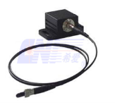
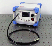
375nm to 940nm Multimode wavelength LED are designed for microscopy and other applications that require multiple color channels.The LED current of each channel can be adjusted independently or modulated via an external voltage.The multi-wavelength LED system offer a compact housing with a backlit, easy-to-read LCD display. They are operated via the buttons on the front panel.
â– UV, Visible, and NIR Versions (from 375nm to 1550nm)
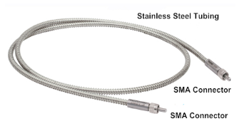
â– The SMA connector is ideal for multimode fiber.
â– Multi-wavelength fiber coupled LED available.
|
|
|
Data Sheet for Single Wavelength LED
|
|
Model
|
Color
|
Nominal Wavelength (nm)
|
Bandwidth FWHM (nm)
|
Typical Φ600um Core Fiber Output Power SMA (mW)
|
Maximum Current CW (mA)
|
Forward Voltage (V)
|
Typical Lifetime (h)
|
|
LFM375
|
UV
|
375
|
9
|
3.0
|
1400
|
3.6
|
~10000
|
|
LFM395
|
UV
|
395
|
16
|
1.0
|
500
|
4.5
|
~10000
|
|
LFM405
|
UV
|
405
|
12
|
4.2
|
1400
|
3.45
|
~10000
|
|
LFM430
|
Violet
|
430
|
15
|
1.0
|
500
|
3.8
|
~10000
|
|
LFM460
|
Royal Blue
|
460
|
25
|
6.0
|
1000
|
3.6
|
~10000
|
|
LFM470
|
Blue
|
470
|
25
|
3.2
|
1000
|
3.2
|
~10000
|
|
LFM500
|
Cyan
|
500
|
30
|
2.2
|
1000
|
3.3
|
~10000
|
|
LFM530
|
Green
|
530
|
33
|
3.0
|
1000
|
3.2
|
~10000
|
|
LFM565
|
Lime
|
565
|
104
|
3.0
|
1000
|
3.1
|
~10000
|
|
LFM600
|
Amber
|
600
|
15
|
1.2
|
1000
|
2.6
|
~10000
|
|
LFM620
|
Red
|
620
|
18
|
5.5
|
1000
|
2.2
|
~10000
|
|
LFM625
|
Red
|
625
|
17
|
3.0
|
1000
|
2.2
|
~10000
|
|
LFM660
|
Deep Red
|
660
|
20
|
4.0
|
1200
|
2.6
|
~10000
|
|
LFM730
|
Far Red
|
730
|
37
|
1.5
|
1000
|
2.3
|
~10000
|
|
LFM808
|
IR
|
808
|
25
|
2.5
|
500
|
3.6
|
~10000
|
|
LFM850
|
IR
|
850
|
30
|
3.0
|
1500
|
3.85
|
~10000
|
|
LFM880
|
IR
|
880
|
50
|
1.0
|
1000
|
1.7
|
~10000
|
|
LFM940
|
IR
|
940
|
37
|
3.0
|
1000
|
2.75
|
~10000
|
|
LFM1050
|
IR
|
1050
|
37
|
2.0
|
600
|
1.4
|
~10000
|
|
LFM1550
|
IR
|
1550
|
102
|
1.0
|
700
|
1.1
|
~10000
|
Note:
1. The above testing data are only for reference, the actual spectrum of LED may change since the temperature or other parameters are different when operating the current.
2.The above data was tested by 600μm core diameter, 0.22 NA multimode fibers. Other core diameter fibers are available on request.
|
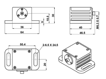
Laser Head
|
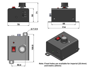
Power Supply
|
|
|
|
64 (L) ×46.5 (W) ×30 (H) mm3
|
114 (L) ×78 (W) ×71 (H) mm3
|
Data Sheet for Multi-wavelength LED
|
|
Parameters
|
Indicators
|
|
Available wavelength (nm)
|
375-940
|
|
Output mode
|
Fiber output
|
|
Fiber core diameter (μm)
|
400, 600, 800, 1000
|
|
Fiber connector
|
SMA905
|
|
Output power (mW)
|
Related to fiber
|
|
Power stability (rms, over 4 hours)
|
<3%, <5%
|
|
Operating mode
|
CW, TTL or Analog on request
|
|
Operating temperature (°C)
|
10~35
|
Dimensions
|
192(L)*241(w)*139.9(H)mm3
|
Input power
|
12VDC 7A
|
Cooling method
|
By air
|
Storage temperature (°C)
|
-20~80
|
Lifetime (hours)
|
10000
|
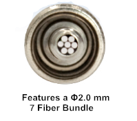
Fiber Specs
|
|
|
Fiber Coupled Led,Fiber Coupled Blue Led,Fiber Coupled Led 1550,Single Mode Fiber Coupled Led
Changchun New Industries Optoelectronics Technology Co., Ltd. , https://www.cnioptics.com


